

Integrating a top-loading washing machine into a bathroom layout requires a precise understanding of vertical clearance, structural mechanics, and moisture dynamics. While these compact appliances excel in narrow footprints, their unique loading mechanism demands specific spatial planning to ensure long-term functionality, comfort, and structural safety.
Understanding Vertical Clearance and Ergonomic Zones
The most critical design constraint of a top-loading washing machine is its vertical axis of operation. Unlike front-loading models that require horizontal swing space for the door, a top-loader requires uninhibited space directly above the unit. When planning the layout, you must account for the lid’s full opening arc, which typically extends the height of the machine by an additional 40 to 50 centimetres.
From an ergonomic standpoint, the loading zone should align with natural human kinetic movement. The ideal height for reaching the bottom of the drum without straining the lumbar spine is determined by the user's height, but generally, a clearance of at least 120 centimetres from the floor to any overhead structure is necessary. If you install cabinetry or shelving above the machine, these structures must be recessed or set back at a depth that prevents the open lid from striking them, which could cause mechanical wear on the hinges or chip the finish of the cabinets.
Microclimate Control and Moisture Dissipation
Every washing cycle releases warm, humid air into the immediate environment, particularly during high-temperature washes or when the cycle ends and the lid is opened. Because warm air naturally rises due to thermal convection, the area directly above a top-loader becomes a microclimatic zone prone to high humidity.
If wooden cabinetry, drywall, or non-moisture-resistant materials are placed directly above the machine without adequate ventilation, they will absorb this rising vapour. Over time, this leads to material swelling, wood rot, or mold propagation. To prevent this, ensure a minimum gap of 15 to 20 centimetres between the fully opened lid and any overhead shelf. Additionally, any surfaces situated in this rising thermal plume should be treated with water-resistant coatings, such as polyurethane sealants or high-gloss latex paints, which prevent water molecules from penetrating the substrate.
Vibration Dynamics and Kinetic Isolation
Top-loading washing machines utilise a suspension system suspended from springs at the top of the outer tub, combined with friction dampers at the base. During the spin cycle, when rotational speeds can exceed 1200 RPM, the kinetic energy must be dissipated correctly. If the machine is squeezed tightly between walls or bathroom cabinets, these vibrations will transfer directly to the building's structure, causing loud structural noise and mechanical strain.
- Lateral Buffer Zones: Maintain a strict clearance of 2 to 3 centimetres on both sides of the machine. This prevents physical contact during off-balance spin cycles when the drum undergoes maximum lateral displacement.
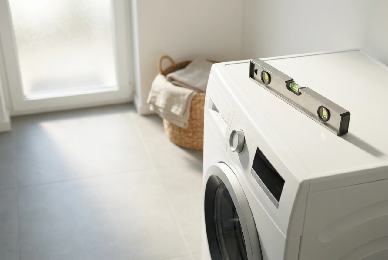
- Precision Leveling: Use a spirit level across both axes of the top plate. Adjust the threaded leveling feet to distribute the machine's mass evenly across all four points of contact, reducing gravitational imbalance.
- Friction Isolation: Placing heavy-duty elastomeric dampening pads under the feet can absorb high-frequency kinetic energy, preventing the machine from migrating across slick tiled floors.
Hydraulic Integration and Standpipe Heights
The plumbing behind a top-loader must be planned with hydrodynamics in mind. Because the machine is typically pushed back into a corner or deep recess, access to the shut-off valves and the drainage point must not be completely blocked. The drain hose must be installed using a proper U-bend or standpipe to prevent sewer gases from entering the machine.
Crucially, the height of the standpipe must comply with gravity-drainage physics. It should be positioned between 60 and 100 centimetres above floor level. If the standpipe is too low, water can siphon out of the drum prematurely during the fill cycle; if it is too high, the internal drain pump will experience excessive backpressure, leading to premature motor failure. Always ensure the hose has a gentle, sweeping curve rather than a sharp kink to maintain unimpeded hydraulic flow.