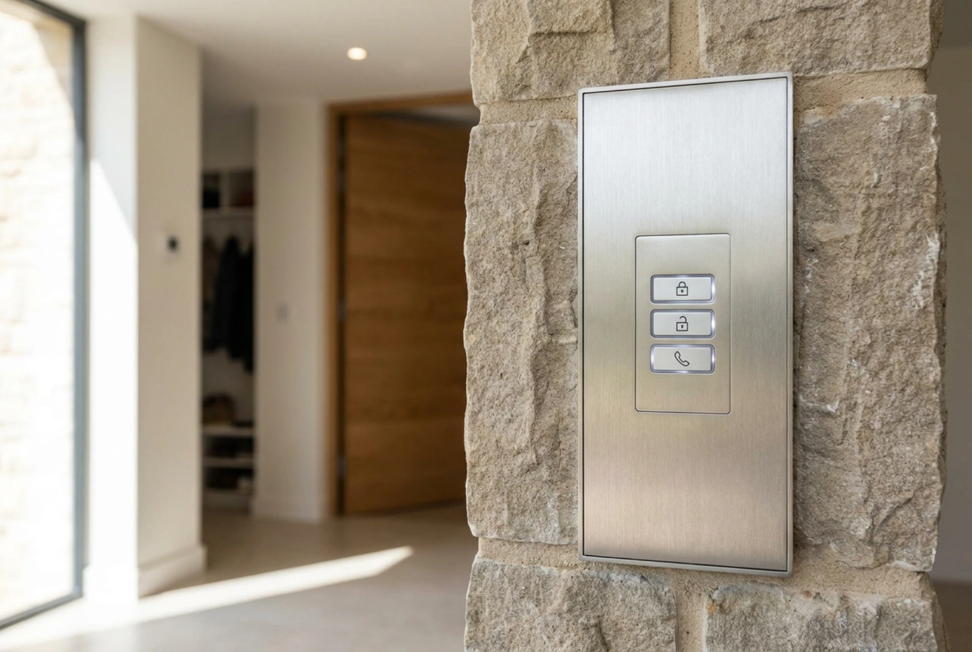


Modern residential security relies heavily on the seamless coordination between entry panels and physical barriers. Understanding the physics and electronics behind gate and wicket intercom systems allows homeowners to ensure reliable operation and diagnose access control issues effectively.
The Core Mechanism of Signal Transmission
At its heart, an intercom system is a closed-loop communication network designed to transmit audio, video, and control signals over defined distances. When a visitor presses the call button on the external entry panel, an electrical signal is sent to the indoor station. Depending on the system architecture, this communication occurs through different electrical paths:
- Analog Systems: These rely on multi-wire cabling (typically 4-wire or 2-wire systems) where dedicated physical conductors carry analog voice signals, power, and trigger currents. Voltage fluctuations on specific lines dictate the actions of the receiver.
- Digital and IP Systems: These convert analog voice and video into digital packets. IP-based systems use Ethernet cables or wireless networks to transmit data protocol packets. The command to open a gate is sent as an encrypted digital instruction rather than a simple raw voltage spike.
Regardless of the signal type, the final action of releasing a lock or activating a gate motor requires transforming a low-power control signal into physical mechanical movement. This process bridges the gap between digital processing and high-force mechanical operations.
How the Wicket Opens: Electromagnetic Latches
The pedestrian gate, or wicket, is typically secured by an electric strike (also known as an electromagnetic latch). This component is integrated into the door frame opposite the mechanical lock bolt. The release mechanism operates entirely on the principles of electromagnetism and mechanical leverage.
When you press the unlock button on your indoor monitor, the intercom system sends a low-voltage electrical pulse (usually 12V AC or DC) directly to the electric strike coil. This electrical current flowing through the coil generates a magnetic field that pulls an internal metal armature, releasing the blocking lever. This allows the visitor to push the gate open without physical key rotation. There are two primary configurations for these latches, selected based on security and safety requirements:
- Fail-Secure (NC - Normally Closed): The latch remains locked when there is no power. It requires an electrical pulse to unlock. This is the standard for perimeter gates, ensuring the property remains secure during power outages.
- Fail-Safe (NO - Normally Open): The latch requires constant electrical power to stay locked. If the power cuts out, the magnetic field collapses, and the lock automatically releases. This configuration is primarily used for emergency escape routes.
Triggering the Driveway Gate: Relay Outputs
Unlike a pedestrian wicket, which simply needs its physical latch released, an automated driveway gate requires a command to initiate a heavy motorized cycle. Intercoms achieve this control safety by using a dry contact relay, isolating high voltage from control circuits.
A relay acts as an electrically operated switch. The intercom unit itself does not provide the power to move the heavy gate. Instead, when the gate release button is pressed, the intercom closes an internal relay contact. This completes a low-voltage control loop connected directly to the automated gate controller.
Once the gate controller detects this closed loop (essentially a momentary short circuit), it activates its internal power relays, drawing high-voltage current from the main domestic supply to run the electric motors. This complete isolation of circuits protects the delicate intercom electronics from the high currents and electric spikes associated with heavy-duty electric motors.
Power Supply, Cable Resistance, and Signal Stability
Reliable operation of both audio-visual communication and lock releasing requires a stable, noise-free power source. Most intercom systems utilize a centralized DIN-rail power supply located in the main electrical switchboard. This device steps down the mains voltage (230V) to a safe, low operating voltage (typically 15V to 24V DC).
Adequate cable cross-section is essential to prevent voltage drops over long distances. If the wire is too thin, the resistance increases, causing a voltage drop that prevents the electric strike from receiving enough current to actuate. Furthermore, signal shielding is crucial to protect the low-voltage communication lines from electromagnetic interference caused by nearby mains power cables running parallel in the same conduits.