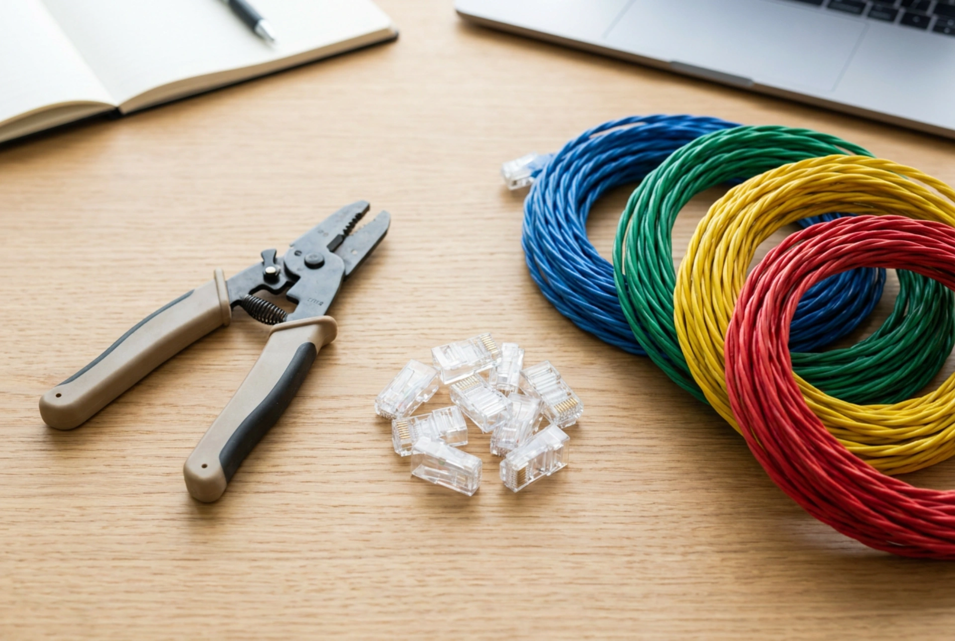


Crimping an Ethernet cable requires physical precision to avoid signal degradation, packet loss, or complete connectivity failure due to incorrect wire sequencing. Mastering the alignment of twisted pairs and understanding the mechanics of copper termination ensures a stable, high-speed network connection capable of supporting maximum bandwidth.
The Physics of Twisted Pairs and Electromagnetic Interference
To understand why precise termination is critical, one must examine the physical principles governing twisted-pair cabling. Ethernet cables contain four pairs of insulated copper wires, twisted around each other at specific ratios. This twisted architecture relies on differential signaling to cancel out electromagnetic interference (EMI) and crosstalk from adjacent wires. When an electric current flows through a wire, it generates an electromagnetic field. By twisting the wires, the fields cancel each other out, and any external noise affects both conductors equally, allowing the receiving network interface to subtract the noise mathematically.
Untwisting these pairs too much during termination ruins this natural noise-cancellation system. According to networking standards, you should never untwist more than 13 millimetres (approx. half an inch) of the cable. Exceeding this limit alters the characteristic impedance of the cable (typically 100 ohms), leading to signal reflections, increased attenuation, and packet retransmissions that degrade local network speeds.
Choosing the Standard: T568A vs. T568B
There are two primary wiring standards used for terminating RJ45 connectors: T568A and T568B. While both perform identically from an electrical standpoint, they differ in the arrangement of the green and orange pairs. For consistency across a modern residential or commercial network, using the T568B standard is highly recommended, as it is the most common layout for patch cables.
The precise pinout order from left to right, looking at the RJ45 connector with the plastic clip facing down and the gold contacts facing up, is as follows:
- Pin 1: White-Orange
- Pin 2: Orange
- Pin 3: White-Green
- Pin 4: Blue
- Pin 5: White-Blue
- Pin 6: Green
- Pin 7: White-Brown
- Pin 8: Brown
Using the same standard on both ends creates a straight-through cable, which is used to connect end devices like computers to switches or routers. Creating a mismatch (T568A on one end and T568B on the other) results in a crossover cable, which was historically used to connect similar devices directly but is largely obsolete due to modern Auto-MDIX ports.
The Step-by-Step Termination Technique
To achieve a professional, error-free termination, you must follow a methodical sequence of physical actions. This minimizes wire damage and ensures a secure physical link.
Step 1: Stripping the Outer Jacket
Use a dedicated cable stripper to remove approximately 2.5 to 3 centimetres of the outer PVC or LSZH jacket. Apply light pressure to score the jacket without cutting into the inner insulation of the copper conductors. Carefully bend the cable at the score line to snap the jacket, then slide it off. Inspect the exposed wires for any cuts; nicked insulation will cause short circuits and require cutting the cable back to start over.
Step 2: Untwisting and Aligning the Conductors
Separate the four pairs. Untwist them only as far as the edge of the jacket. Using your thumb and index finger, straighten each wire individually. This physical straightening is crucial because kinked wires will not slide smoothly into the channels of the RJ45 connector. Arrange the wires in the exact T568B sequence, keeping them flat and parallel to each other.
Step 3: Trimming to Length
Hold the straightened, ordered wires tightly between your thumb and forefinger. Use a sharp, flush cutter to trim the wires in a perfectly straight, horizontal line, leaving exactly 12 to 14 millimetres of exposed wire from the edge of the jacket. A straight cut ensures that all eight conductors reach the end of the RJ45 connector channels simultaneously, guaranteeing solid contact with the gold pins.
Step 4: Inserting and Crimping
Slide the wires into the RJ45 connector with the flat side (contacts) facing up. Ensure that each wire enters its corresponding channel. Push the cable firmly until the copper ends are visibly touching the back wall of the connector. Crucially, the outer jacket of the cable must extend about 6 millimetres inside the connector, past the internal plastic wedge. When crimped, this wedge secures the jacket, providing vital strain relief that prevents physical tension from pulling the copper conductors away from the contacts.
Insert the prepared connector into the crimping tool and squeeze the handles firmly. The tool drives the gold-plated metal teeth down, piercing the insulation of each individual wire to establish a gas-tight electrical connection, while simultaneously pressing down the strain-relief wedge onto the outer jacket.
Verification and Troubleshooting
Always perform a visual and mechanical check post-crimp. Looking through the transparent plastic of the RJ45 connector, verify that all eight copper conductors are flush against the end of the connector and that the wire order remains correct. Finally, use a low-voltage cable continuity tester to verify wire mapping, ensuring there are no open circuits, short circuits, or crossed wires along the length of the cable.