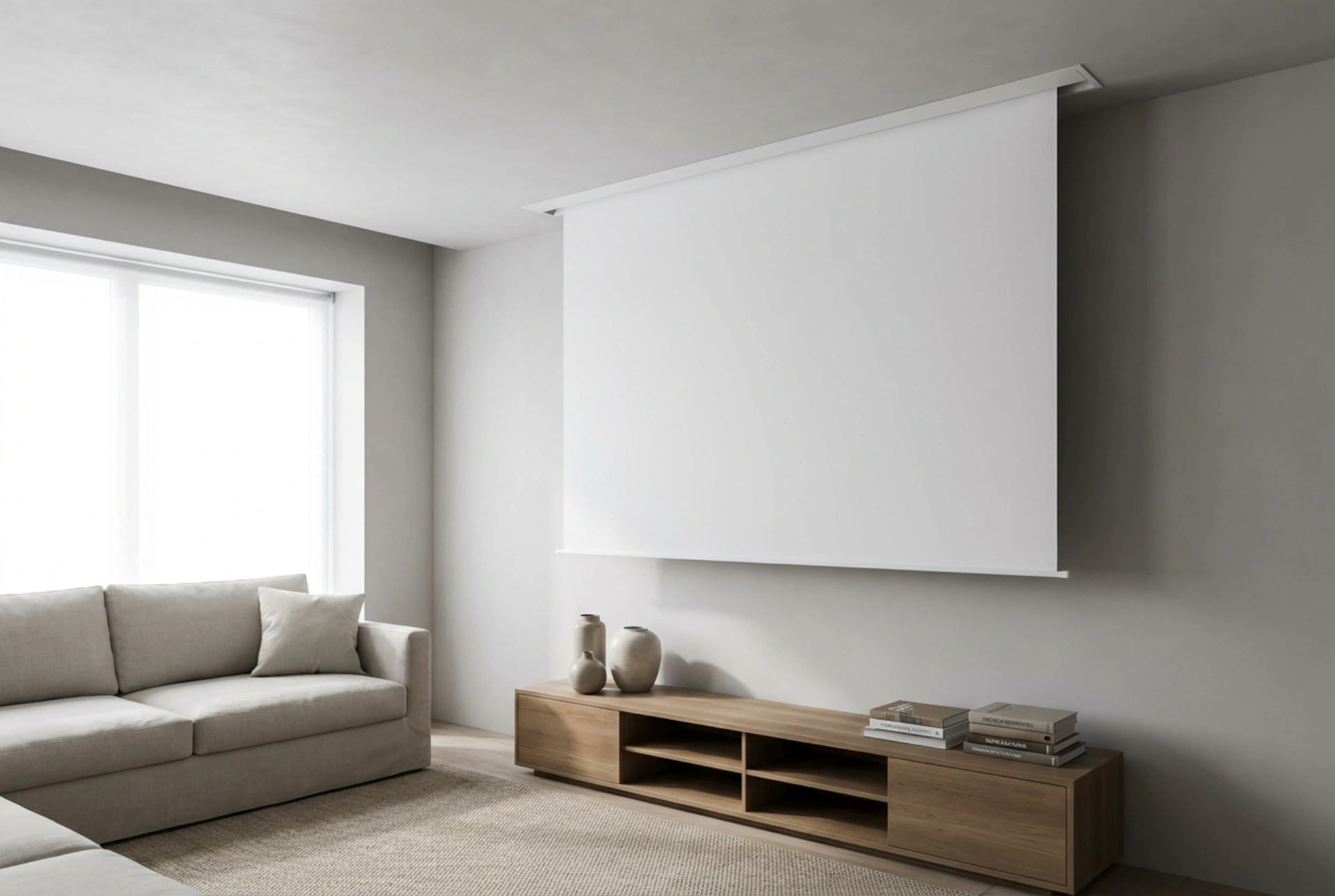


Installing an electric ceiling-mounted projector screen requires precise structural alignment and an understanding of load distribution to prevent ceiling sagging or dynamic mechanical failure. This guide explains how to secure the heavy casing to various ceiling types and align it perfectly for distortion-free projection.
Understanding Structural Load and Material Mechanics
An electric projector screen contains a heavy motor, a solid roller tube, and weighted bottom bars, making it significantly heavier than manual pull-down screens. When the motor starts or stops, it generates dynamic rotational torque, which increases the stress on the ceiling anchors. Therefore, standard drywall plugs are insufficient and dangerous for this application.
For concrete ceilings, expansion anchors made of steel are the ideal choice. They grip the dense material through friction and mechanical interlock, comfortably handling both static weight and motor vibrations. For plasterboard (drywall) ceilings, you must locate the underlying wooden joists or steel studs using a stud finder. If mounting directly to plasterboard is unavoidable, use heavy-duty steel spring toggle bolts that distribute the weight over a wider surface area on the hidden side of the board. Never hang a motorized screen from drywall alone without structural anchoring.
Precision Alignment to Prevent Keystoning and Warping
Before drilling any holes, you must establish a perfectly level plane. If the screen casing is even slightly tilted, the fabric will hang unevenly, causing ripples and tension lines that distort the projected image. Furthermore, an unlevel screen forces the motor to pull unevenly, wearing out the internal bearings prematurely.
Using the Three-Axis Alignment Method
- Horizontal Level: Use a high-quality spirit level or a self-levelling cross-line laser level placed parallel to the ceiling. Align the laser line with the planned bracket locations to ensure the left and right sides sit at the exact same elevation.
- Perpendicular Alignment: Ensure the screen face hangs exactly 90 degrees perpendicular to the projector's lens path. Even a tiny angular deviation will cause keystoning, where one side of the image is wider than the other.
- Offset Clearance: Measure the distance from the wall to clear any obstacles like picture frames, window sills, or televisions. Ensure the screen drop clearance is calculated with at least 5 centimetres of buffer space.
Step-by-Step Mounting Process
Most electric screens utilize either sliding brackets or fixed end-cap brackets. Sliding brackets offer more flexibility as they allow you to align the mounting points directly with ceiling joists regardless of the screen's exact lateral position.
Marking and Pre-Drilling
Hold the mounting brackets against the ceiling at the marked laser line. Mark the exact centres of the screw holes. If you are mounting into wooden joists, drill pilot holes slightly smaller than the core diameter of your wood screws to prevent the wood from splitting. For concrete, use a rotary hammer drill with a masonry bit matching the diameter of your expansion anchors.
Securing the Brackets
Insert the anchors into the drilled holes. Drive the heavy-duty lag screws or bolts through the brackets into the anchors. Tighten them firmly, but avoid over-torquing, which can strip the threads in wood or crack the plasterboard. Verify that the brackets are flush against the ceiling and completely immoveable.
Hoisting and Locking the Screen
Because of the length and weight of motorized screen casings, this step requires two people. Carefully lift the screen housing into the brackets. Ensure the locking mechanism—whether it is a click-in spring lock or a bolt-through system—engages completely. Tighten any safety set-screws to prevent the housing from sliding laterally during operation.
Power Routing and Fabric Limit Adjustments
Once structurally secured, the screen requires power. Most consumer units feature a standard power cord with a moulded plug, which should be routed to a nearby outlet using surface-mounted cable trunking to protect the cord from physical wear. If hardwiring is desired, this must be handled in compliance with local structural codes without altering the internal safety components of the screen motor.
Finally, adjust the mechanical limit switches located on the side of the screen casing. These rotary switches control how far the motor rolls the screen down and up. Adjust them gradually using the provided hex tool to ensure the weighted bottom bar stops just before hitting any floor obstacles, and retracts fully without putting excessive tension on the fabric roll, preventing long-term stretching.