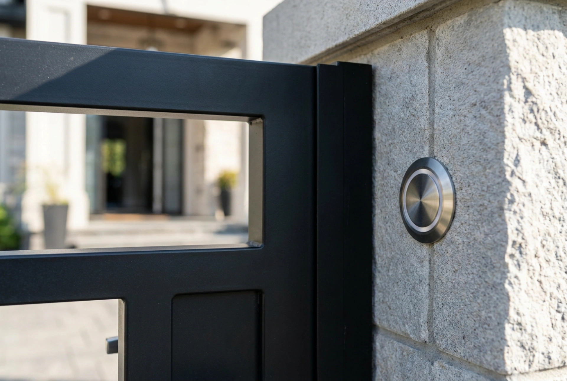


Setting up a video intercom system requires meticulous physical and infrastructural planning before any hardware is mounted. Ensuring correct cabling, proper conduit routing, and strategic positioning guarantees long-term system reliability and optimal camera coverage without signal degradation.
Choosing the Correct Cabling: Materials and Physics
The foundation of any reliable video entry system lies in the physical medium transporting the data and power. Standard indoor network cables degrade rapidly when exposed to subterranean moisture and temperature fluctuations. For underground routing from the house to the gate pillar, you must use gel-filled (flooded) Category 5e or Category 6 UTP/FTP cables designed specifically for direct burial.
The gel compound inside these cables acts as a hydrophobic barrier, preventing water migration if the outer polyethylene (PE) jacket suffers micro-fissures. Additionally, copper core thickness (measured in AWG) is critical. For distances exceeding 50 metres, standard 24 AWG wire may suffer from voltage drop due to inherent electrical resistance, causing the screen to flicker or the electric strike to fail. In such scenarios, choosing a cable with thicker 22 AWG copper conductors ensures steady power delivery by minimizing resistive losses.
Conduit Routing and Moisture Management
Cables should never be buried loose in the soil. They must run inside a dedicated, durable protective conduit. When installing this conduit, avoid sharp 90-degree angles which create high friction points, making it impossible to pull or replace cables in the future. Instead, use wide, sweeping bends with a radius of at least ten times the conduit diameter.
Condensation is an inevitable physical phenomenon inside underground pipes due to temperature differentials between the warm earth and cold air. To prevent water from pooling around the cable connections, the conduit should slope slightly away from the gate pillar toward a gravel drainage pocket. Seal the conduit ends with a non-hardening duct sealing compound to stop humid air, insects, and rodents from entering the channel and nesting near the sensitive electronic terminals.
Optimising Mounting Height and Camera Physics
The positioning of the external station dictates the utility of the video feed. A common mistake is mounting the camera too high, resulting in views of the tops of heads rather than faces. The optimal optical axis height is between 1.5 and 1.6 metres from the finished ground level. This height accommodates the average human stature and allows the lens to capture both tall adults and shorter visitors within its vertical field of view.
Light physics must also be accounted for. If the gate faces directly east or west, the camera lens will experience severe glare and backlighting during sunrise or sunset, blinding the sensor. To mitigate this, prepare the mounting site on a side pillar perpendicular to the street, or plan for a protective rain hood that doubles as a sun shield, preventing direct sunlight from striking the lens elements and causing internal reflections.
Preparing the Electric Strike and Power Distribution
An electronic gate access system relies on an electric strike or magnetic lock at the gate frame. This mechanical component requires its own low-voltage power circuit. When preparing the wiring layout, run separate twisted pairs for the audio/video signal and the power supply of the lock. Placing high-draw lock power lines parallel to unshielded signal wires can induce electromagnetic interference, leading to audio hums or video lines.
Ensure that the pocket for the electric strike in the gate post is precisely aligned with the lock latch. Any physical binding or tension on the strike plate will prevent the internal solenoid from releasing when electrical current is applied. Leaving a physical tolerance of two to three millimetres prevents gate expansion due to summer heat from jamming the mechanism.