

Positioning an outdoor weather station sensor correctly is the difference between receiving highly accurate meteorological data and getting skewed readings influenced by local microclimates. Understanding the thermodynamic properties of materials and the fluid dynamics of wind movement ensures your sensor records the true ambient conditions rather than the artificial heat of its surroundings.
The Physics of Thermal Radiation and Microclimates
To capture accurate temperature data, you must understand how different surfaces interact with solar energy. Materials such as brick, concrete, tarmac, and dark wooden decking possess high thermal mass and low albedo. This means they absorb shortwave solar radiation during the day and gradually re-emit it as longwave thermal radiation (sensible heat) well into the evening. Mounting a sensor too close to a house wall or above a patio will result in artificially elevated temperature readings.
To avoid this thermal interference, the sensor should ideally be positioned over a natural, living surface such as grass or soil. Vegetation undergoes evapotranspiration, a natural cooling process where water evaporates from leaves, keeping the surrounding air temperature representative of the environment. If you must mount the sensor near a building, maintain a minimum horizontal distance of two to three metres from any vertical structures to prevent the sensor from bathing in the building's thermal envelope.
Optimising Height and Ventilation for Temperature and Humidity
The microclimate changes rapidly with altitude, even within the first few metres above the ground. At ground level, moisture evaporating from soil and grass creates a high-humidity boundary layer, while night-time radiative cooling makes the air closest to the ground significantly colder than the air just a couple of metres higher. To standardise these variables, professional meteorological bodies recommend mounting temperature and humidity sensors at a height of 1.25 to 2 metres above the ground.
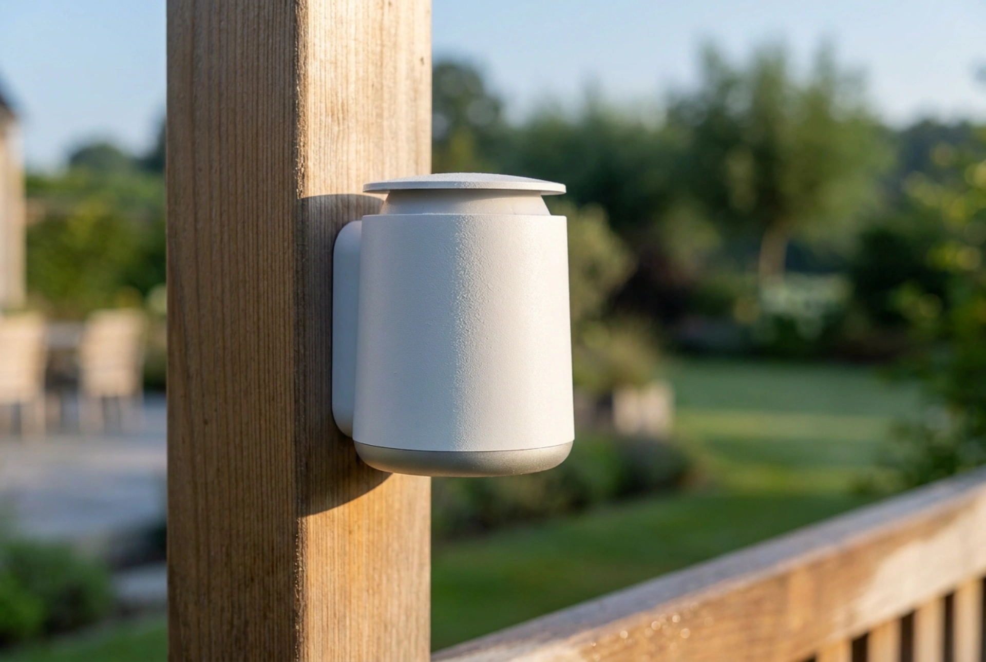
At this height, the sensor is elevated beyond the immediate ground boundary layer but remains low enough to avoid the higher wind speeds found further up. However, height alone is not enough; the sensor must be shielded from direct sunlight. Direct exposure to solar radiation will heat the housing far beyond the ambient air temperature. A multi-plate solar radiation shield is essential. This device uses a series of white, nested, louvered plates that block direct and reflected sunlight from reaching the internal probe while allowing wind to pass through freely, utilizing natural convection to constantly refresh the air around the thermistor.
Mitigating Wind Obstructions and Turbulence
If your weather station includes an anemometer (wind speed sensor) or a wind vane, fluid dynamics must dictate its placement. Wind does not flow smoothly around obstacles; when air hits a fence, wall, or tree, it creates a turbulent wake zone on the leeward side. This turbulence can extend horizontally to a distance of up to ten times the height of the obstacle.
To obtain reliable wind data, the anemometer should ideally be placed at least ten metres above the ground, clear of any local obstructions. Since this is often impractical in residential settings, the practical alternative is to mount the wind sensor on a mast that extends at least two to three metres above the roofline of the tallest nearby structure. If mounted on a vertical mast, ensure the mount is exceptionally rigid. Fluctuations in wind can cause a flexible mast to sway, which introduces mechanical noise and errors into wind speed measurements.
Leveling and Securing Rain Gauges
Precipitation measurement is highly sensitive to mechanical positioning. Most automated weather stations employ a tipping-bucket mechanism, where a small internal lever tips back and forth as it fills with water, sending an electrical pulse for every increment (usually 0.2 mm) of rain. For this physical mechanism to work correctly, the entire unit must be perfectly level.
If the rain gauge is tilted even slightly, the gravity-fed tipping mechanism will require more water to tip in one direction than the other, leading to systematic under-reporting of rainfall. Use a circular bubble level during installation to verify both the horizontal and vertical axes of the gauge. Additionally, the gauge must be mounted away from any overhanging tree branches or roof eaves. These structures can block rain during windy conditions or, conversely, channel concentrated drips into the collector long after the rain has stopped, completely invalidating the data.